Indeed, field measurements of working plane illuminance, or Lux Level, are essential in a range of scenarios, including verification of design requirements, understanding complaints about lighting, and aiding designers, installers, and end users. Various methods have been developed for the field measurement of interior and exterior lighting, with commonly used standards being BEE, CIBSE, IES, and DIN code.
While these methods are often similar or slightly derivative of one another, they each have unique characteristics. Most require the measurement of illuminance at grid points on the working-plane height or floor, but the size of the grid and the positioning of the measurement points can vary. For instance, the IES method and its derivatives position the grid according to luminaire locations, while the CIBSE and DIN methods position the grid according to room size. The techniques used to analyze the results of field measurements also differ between methods.
When measuring both interior and exterior light levels, it’s critical to consider the following points to ensure accurate results:
- Use the same calibrated illuminance measurement meter (Lux Meter) whenever possible. If the same meter isn’t available, try to use the same make and model of calibrated meter to minimize errors.
- Ensure that no objects or materials are blocking light to the meter head when taking measurements. It’s recommended to use a remote meter head cabled to the meter body to prevent the operator from blocking the meter’s “view” of the lighting system being measured.
- For outdoor lighting, it’s essential to conduct illuminance measurements at night (in proper darkness).
- For indoor lighting, you can use the lights ON and lights OFF technique, provided daylight variation isn’t significant and the survey time isn’t too long.
- If you’re measuring the installation of fluorescent discharge lamps, you should switch on the lamps at least 30 minutes before the measurement to allow them to warm up completely.
- Often, the measuring plane may not be specified or even non-existent. In these situations, you need to define a measurement height, typically 0.8 to 1 meter from the ground or floor level.
- The lux measurement procedure requires positioning a meter’s sensor on the surface or location where you want to measure the incident light. The sensor should face the light source at a right angle. If the sensor isn’t perpendicular to the light, the measurement will be incorrect, although some lux meters have a cosine correction to account for the angle.
- For meters requiring a color correction factor (CCF), there may be a means of inputting the CCF to adjust the result for LEDs or fluorescent lights. If not, you will need to manually multiply the measured lux by the CCF.
By adhering to these considerations, you can ensure accurate and reliable results from your light level measurements, thereby helping to improve the lighting conditions in your chosen environment.
Indoor Illumination (Lux Level) Measurement
As per Room Index Method (as per BEE Code / CIBSE Code):
- This method is more suitable where measuring Plan / Points for an interior is more rectangular than square. First, we need to be found Room Index.
- Based on the room index, the minimum number of illuminance measurement points is decided by Room Index Number
- Room Index (RI) = (L x W) / H x (L+ W)
- Where L = Length of Room
- W = Width of Room
- H= Height of the luminaires above the plane of measurement
|
Table 1: Number of points for measuring illuminance |
||
| Room index | Minimum number of measurement points | |
| For ± 5% accuracy | For ± 10% accuracy | |
| RI < 1 | 8 | 4 |
| 1 < RI < 2 | 18 | 9 |
| 2 < RI < 3 | 32 | 16 |
| RI > 3 | 50 | 25 |
Sample calculation
- Measure Illumination Level of an office room have length, L = 7.5 m and width W = 5 m,
- Solution:
- Suppose Height of Illumination from Floor is 2 Meter
- Room Index RI = (L x W) / H x (L+ W)
- Room Index RI = (7.5 x 5) / 2 x (7.5+ 5)
- Room Index RI = 1.5
- From Table 1 minimum Illumination Measure Points should be 18 No’s
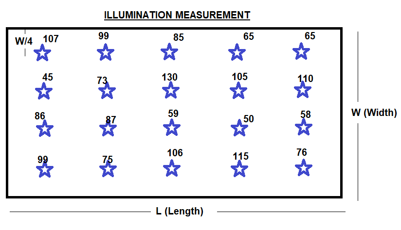
- The illuminance measurements Points with Measured Value in Lux are marked on the grid.

|
Measurement Reading Details |
||||
| 107 Lux | 99 Lux | 85 Lux | 65 Lux | 65 Lux |
| 45 Lux | 73 Lux | 130 Lux | 105 Lux | 110 Lux |
| 86 Lux | 87 Lux | 59 Lux | 50 Lux | 58 Lux |
| 99 Lux | 75 Lux | 106 Lux | 115 Lux | 76 Lux |
| Min | 45 Lux | |||
| Max | 130 Lux | |||
| Average | 85 Lux | |||
| U1=MIN/AVG | 0.5 Lux | |||
| U2=MIN/MAX | 0.3 Lux | |||
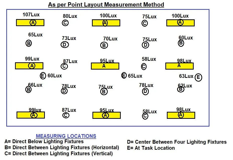
As per Point Layout Method
- Creating a layout for taking lighting measurements in an office space can be quite complex, as different areas may require different levels of illumination, and the physical layout of the area can also influence where you measure. However, as a guideline, the following strategies can be used to identify measurement points on desks and other work surfaces that best represent the lighting conditions across the office space.
- For Desk Areas: The measurements should be taken from the point on the desk where the person is most likely to be working, such as in front of a computer monitor. For a single desk, consider multiple points such as the center and corners. For a larger workstation area, more points may need to be measured, typically forming a grid across the surface.
- For Non-Desk Task Areas: Consider the purpose of the area and where the task is most likely to take place. For example, in a kitchen area, measurements should be taken from countertop surfaces, and for a reading area, the light level should be measured where the book would be placed.
- For Walkways or Corridors: For these transitional spaces, a measurement should be taken from the middle of the walkway or corridor at about 1 meter above the floor. These measurements are important because they can influence the perceived brightness of the adjacent areas.
In regards to vertical measurements, selecting a plane that represents the lighting condition in the area is crucial. This can be achieved by selecting a vertical plane, typically a line directly between two light fixtures, and setting a line of points at 1.5 meters above the site surface at each corresponding horizontal measurement point.
Remember, while these guidelines can help, the specific requirements of your office or workspace may require adjustments. Always consider the nature of the work being conducted and the needs of the individuals using the space when deciding where to measure.

|
Measurement Reading Details |
||||
| 107 Lux | 80 Lux | 100 Lux | 75 Lux | 100 Lux |
| 65 Lux | 73 Lux | 70 Lux | 75 Lux | 60 Lux |
| 99 Lux | 87 Lux | 95 Lux | 58 Lux | 98 Lux |
| 60 Lux | 65 Lux | 63 Lux | ||
| 66 Lux | 78 Lux | 75 Lux | 78 Lux | 62 Lux |
| 99 Lux | 87 Lux | 95 Lux | 58 Lux | 98 Lux |
| Min | 58 Lux | |||
| Max | 107 Lux | |||
| Average | 80 Lux | |||
| U0 or U1=MIN/AVG | 0.7 Lux | |||
| Ul or U2=MIN/MAX | 0.5 Lux | |||
